Introduction to Logic Gates
Logic gates form the backbone of digital electronics, where binary inputs are processed to produce specific outputs. They are designed to perform fundamental Boolean functions, which are crucial in computational operations. Common types of logic gates include AND, OR, NOT, NAND, NOR, XOR, and XNOR.
Among these, the XOR gate holds a special place in complex circuit designs due to its unique behavior. The XOR gate controlled inverter function stands out in applications that require conditional inversion of signals, making it a key component in various error-checking mechanisms and encryption processes.
The focus of this article is on the XOR gate’s ability to behave as a controlled inverter, setting it apart from other logic gates like the NAND or NOT gates.
What is an Inverter?
An inverter, also known as a NOT gate, is a basic logic gate that inverts the input it receives. If the input is 0, the output is 1, and vice versa. This inversion of the input signal makes inverters essential in controlling signal flows in logic circuits. The simplest form of an inverter is the NOT gate, which provides unconditional inversion.
However, the XOR gate controlled inverter operates differently. Instead of inverting the input unconditionally like the NOT gate, the XOR gate allows conditional inversion. This means the XOR gate inverts the input only when specific conditions are met, making it more versatile and practical for certain applications where flexibility is needed.
Understanding the XOR Gate
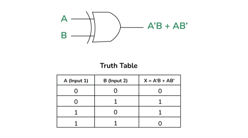
The XOR gate, short for “Exclusive OR,” outputs true (1) only when the two inputs are different. This is in contrast to the regular OR gate, which outputs true when at least one input is true. Below is the truth table for an XOR gate:
| Input A | Input B | XOR Output |
|---|---|---|
| 0 | 0 | 0 |
| 0 | 1 | 1 |
| 1 | 0 | 1 |
| 1 | 1 | 0 |

The XOR gate’s behavior comes from its mathematical expression, which is based on binary addition without carry-over. Mathematically, the XOR gate performs:
A⊕B=(A+B)*mod 2
This equation highlights how the XOR gate operates like binary addition but discards carry operations. In digital circuits, the XOR gate’s controlled behavior makes it useful in systems where selective inversion is needed.
This equation highlights how the XOR gate operates like binary addition but discards carry operations. In digital circuits, the XOR gate’s controlled behavior makes it useful in systems where selective inversion is needed.
Why is the XOR Gate Called a Controlled Inverter?

The XOR gate controlled inverter behavior arises when one input is fixed at 1. Let’s take a deeper look at the mathematical justification for this:
When one input is set to 1 (A = 1), the XOR function becomes:
1⊕B=B
This shows that when A is 1, the XOR gate effectively inverts B, making the XOR gate behave like a controlled inverter. This conditional inversion is highly useful in complex digital circuits where signal inversion is needed only under specific circumstances.
The mathematical proof reinforces the unique nature of XOR as a controlled inverter and explains why it is preferred over simpler gates like NOT in certain designs. This behavior is used in circuits such as multiplexers, which route signals based on control inputs, and parity generators, where XOR gates invert bits based on the control configuration.
How Can XOR Be Used as an Inverter?
To use the XOR gate controlled inverter, set one input of the XOR gate to 1. This setup ensures that the XOR gate will invert the second input. Here’s an example circuit:
- Input A: Constant 1
- Input B: Signal to be inverted
- Output: Inverted signal
In real-world systems, this configuration is used in cryptographic systems like the Vernam cipher, where XOR is used to invert data based on a key input. Additionally, XOR gates are essential in constructing phase detectors, where signals are conditionally inverted to determine phase differences between inputs.
Comparison with Other Inverter Gates
The XOR gate controlled inverter differs from other inverting gates, such as the NAND gate and the NOT gate. A NAND gate can also act as an inverter when both its inputs are tied together, but it lacks the conditional flexibility of XOR. A NAND gate inverter can be modeled as:
A⋅A=A
While the NAND gate can invert inputs, it doesn’t offer the same control over the inversion that the XOR gate does, making XOR more suitable for situations requiring dynamic inversion based on control inputs.
The NOT gate, on the other hand, is the simplest form of an inverter, with no control over its output; it always inverts the input. In contrast, the XOR gate controlled inverter inverts only when the control condition (Input A = 1) is met, making it more adaptable for complex logic circuits.
What is the Function of an Inverter in Logic Gates?
Inverters are critical in signal processing, where they alter signal polarities, helping to perform logic functions like AND, OR, and XOR. In applications like data transmission, an inverter can correct signal errors, flip bits, or toggle between high and low states based on circuit requirements.
Inverters like the XOR gate controlled inverter are widely used in processors and communication devices, where conditional signal inversion allows for more efficient data handling and error checking. For instance, XOR gates are essential in implementing Hamming codes for error detection and correction in memory storage devices.
Other Logic Gates as Inverters
Besides XOR, the XNOR gate can also function as a conditional inverter. The XNOR gate outputs true when both inputs are the same, and false when they are different. When one input is fixed, the XNOR gate can invert the second input.
However, gates like AND, OR, and NOR do not offer inverting behavior unless they are paired with a NOT gate or structured in specific configurations. Therefore, XOR and XNOR gates are more commonly used in scenarios requiring conditional inversion.
Real-Life Examples of XOR Gates

- Cryptography and Encryption: XOR gates play a central role in encryption algorithms such as the Vernam cipher, where plaintext is XORed with a key to produce ciphertext. The XOR gate controlled inverter ensures that signals are dynamically inverted based on key inputs, enhancing encryption security.
- Parity Generation and Checking: XOR gates are used in parity generators to detect errors in transmitted data. By inverting specific bits based on control inputs, the XOR gate helps ensure data integrity.
- Phase Detectors in Communication Systems: XOR gates are essential in phase-locked loops (PLLs) for frequency synthesis. In this application, the XOR gate controlled inverter measures phase differences between input signals, inverting one signal to achieve synchronization.
Conclusion
The XOR gate’s unique ability to conditionally invert inputs makes it a controlled inverter, distinguishing it from simpler gates like NOT or NAND. Its versatile application across digital circuits, cryptographic systems, and error-detection mechanisms demonstrates the critical role the XOR gate controlled inverter plays in modern electronics. Understanding how and why XOR functions as a controlled inverter opens up new possibilities for optimizing digital logic systems.
FAQs on XOR gate controlled inverter
Why is the XOR gate called a controlled inverter?
The XOR gate inverts its input when one input is fixed at 1, making it a controlled inverter.
Why is it called an inverter gate?
It’s called an inverter gate because it flips or inverts the input signal.
Why is the XOR gate called an inverter?
The XOR gate acts as an inverter when one input is set to 1, inverting the other input.
What is the inverter of the XOR gate?
The XOR gate itself acts as an inverter when one of its inputs is set to 1.
Why is the given circuit called an inverter?
The circuit is called an inverter because it changes the input signal from 0 to 1 or 1 to 0.
Why is the XOR gate called an inverter?
The XOR gate inverts the second input when the first input is set to 1, hence behaving like an inverter.
Why is a NAND gate an inverter?
A NAND gate can act as an inverter when both inputs are tied together.
What do you mean by a controlled inverter?
A controlled inverter selectively inverts the input based on a control signal.
What logic gate can function as a controlled inverter?
The XOR gate can function as a controlled inverter.
What is an inverter in a control panel?
An inverter in a control panel changes the input signal from high to low, or vice versa, for proper signal flow.
How can we use the XNOR gate as an inverter?
Set one input of the XNOR gate to 0, and it will invert the other input.
What is the function of an inverter in logic gates?
The inverter reverses the input signal from 0 to 1 or 1 to 0.
Why is XOR called exclusive?
XOR is called exclusive because it outputs true only when inputs are different.
What is an example of a XOR gate in real life?
XOR gates are used in encryption and error detection systems.
Which logic gate cannot be used as an inverter?
AND and OR gates cannot be used as inverters.
What is another name for an inverter gate?
Another name for an inverter gate is a NOT gate.
Why is a NOT gate known as an inverter?
The NOT gate always inverts or flips its input, hence it’s called an inverter.
How can XOR be used as an inverter?
By setting one input to 1, XOR inverts the other input.
Why is XOR so special?
XOR is special because it performs conditional inversion and is used in error detection and cryptography.
What is the specialty of the XOR gate?
The XOR gate outputs true only when inputs are different, and can act as a controlled inverter.
Why is it called an inverter?
An inverter flips the input signal, converting 1 to 0 and vice versa.


